Chevrolet Cobalt Service & Repair Manual: Vehicle Visual Inspection Procedures
Gasoline & Alternative Fuel Engine Vehicles
Visual Inspection
| To ensure proper operation of
all emission control system components it is required to perform a visual
inspection. Refer to the Vehicle Emission Control Information Label and
the Emission Control Application Charts in this manual for emission control
component installation. |
| During this inspection, vacuum
hoses should be inspected for condition and proper connections. All hoses
should be free of pinches, cuts, cracks and disconnections. An inspection
mirror may be required in areas where hoses are difficult to view. Emission
control vacuum hose routing should be confirmed by referring to the vacuum
hose routing on the Vehicle Emission Control Information or Vacuum Hose
Routing Label, which should be affixed in the vehicle's engine compartment.
On earlier models and in cases where the Vacuum Emission Control Information
Label is missing or unreadable and a replacement label is unavailable,
refer to the appropriate MOTOR Emission Control Manual, Engine Tune Up &
Electronics Manual, Engine Performance & Driveability Product or Emission
Control Vacuum Hose Routing and Component Locator Manual for the model being
inspected. If a vacuum hose routing modification has been authorized by
the vehicle manufacturer, an Emission Control Modification Label should
be affixed to the engine compartment noting this change. Any other modifications
to the vacuum hose routing should be considered suspect. |
| Engine compartment wiring harnesses
should be inspected for proper routing and loose or disconnected electrical
connectors. Wiring should also be inspected for burned or chafed insulation
and to ensure it is not pinched or in contact with sharp edges or exhaust
manifolds. Inspect ignition wiring for heat damage and deterioration. Also
note condition of distributor cap. |
| Inspect for disconnected choke
assemblies and other carburetor components. Also inspect for unauthorized
modifications to the fuel system. On models with AIR pump, inspect for missing,
improperly adjusted or worn pump drive belt. On models with EGR, ensure
all components are properly connected. While viewing underhood area with
engine operating, inspect for engine misfire, unstable idle speed and abnormal
noises. Also note any fuel, coolant, engine oil, vacuum, exhaust or compression
leaks, as these may affect engine or emission control system operation. |
| Inspect exhaust system for deterioration,
damage and exhaust leaks. On models that require a catalytic converter,
ensure the converter and fuel tank filler neck restrictor are in place.
Also inspect for unauthorized modifications. |
| When in passenger compartment
of vehicle, inspect instrument panel for any Check Engine, Malfunction Indicator
Lamp (MIL), Power Loss or Emission Reminder Indicator lamp lighting, which
could indicate a faulty or inoperative emission control or related system. |
Vehicle Emission Control Information Label
| Passenger cars and light duty
trucks are equipped with a vehicle emission control information label, affixed
to the engine or the engine compartment. The information on this label includes,
label code, model year, certification standards (Federal, California, Canada),
engine family, engine size, engine tune up adjustment and specifications,
applicable emission control components or systems, and, in some cases, the
emission control system vacuum hose routing, Figs. 1 through
3. |
| When installing a replacement
emission control information labels on a vehicle that has a defaced, damaged
or missing label, the label intended for that particular vehicle must be
installed. Installation of label other than the one which is intended for
the vehicle is in violation of state and federal laws, which may result
in severe fines and penalties being imposed. It should also be noted that
California law states that no person other than the manufacturer, or person
authorized by the manufacturer, shall install a vehicle emission control
label on any motor vehicle. Persons found in violation of the California
law are subject to a fine and/or imprisonment. |
| Some manufacturers will affix
a separate emission vacuum hoses routing label to the engine compartment.
If a modification to the vehicle emission control system has been authorized
by the vehicle manufacturer, an Emission Control Modification Label should
be affixed to the engine compartment noting this change. |
| California BAR (Bureau of Automotive
Repair) and other state emission control inspection and maintenance laws
may require an additional certification label to be affixed to the vehicle.
These labels may be required on kit vehicles, gray market vehicles or vehicles
in which an approved modification or component change may have been performed. |
Emission Calibration Label
| The emission calibration label,
located in the engine compartment, on the engine valve cover or on the lefthand
or righthand door or door pillar, depending on model of vehicle. This label
will list the engine year, calibration code and revision level, Figs.
4 and 5. This number is used to determine
calibration adjustments, specifications and components that are specific
to a particular engine. |
Air Cleaner (ACL) Thermostatic Type
| The thermostatically controlled
air cleaner system, Fig. 6, provides heated air to
the carburetor or throttle body during engine warm-up. This system consists
of a heat stove wrapped around the exhaust manifold, a heated air tube,
an air temperature sensor and a vacuum motor operated air valve. The air
valve in the air cleaner blends air warmed from the heat stove on the exhaust
manifold with outside air. The air valve can close the opening to either
air source, or blend a mixture of both depending upon operating conditions. |
| Inspect exhaust manifold shroud,
hot air tube and air cleaner for proper installation, tampering and damage.
Ensure all vacuum switches are properly installed and vacuum hoses are connected
and properly routed. |
Air Injection System (AIS)
| The air injection system is used
to reduce CO (carbon monoxide) and HC (hydrocarbon) emissions by adding
a controlled amount of air to the exhaust gases. This additional air causes
further oxidation of the exhaust gases with an appreciable reduction in
CO and HC emissions. On some models, the extra air in the exhaust gases
provided by the air injection system is used to increase the efficiency
of catalytic converter operation. |
Air Pump (AIR) System
| The air pump type system, Fig.
7, uses a belt driven vane type pump which usually mounts
to the front of the engine. Some later models may use an electrically powered
type pump, Fig. 8. The system may include a check valve,
a bypass or diverter valve, air tubes or manifold and check valves to route
the air to the engines exhaust ports. Some engines use internally drilled
passages to deliver the air to the ports. On models equipped with a catalytic
converter, a vacuum differential valve may also be used. Some models such
as heavy duty trucks may use more than one air pump. |
| The system should be inspected
for proper installation of the air pump, control and check valves and air
tubes or manifolds. Air hoses and vacuum control system hoses should be
inspected for condition and proper connections. The pump drive belt should
also be inspected for proper installation. |
Pulsed Secondary Air Injection (PAIR) System
| The PAIR system, Figs.
9 and 10, does not used an air pump. Pulsations
in the exhaust system or the reciprocating motion of an engine piston are
used by the PAIR valve to draw air into the exhaust. The system usually
consists of a PAIR valve, check valve(s) and air tubing or hoses, to deliver
the air to the exhaust ports or exhaust system. |
| Ensure all components are properly
installed. Inspect air and vacuum hoses for condition and proper routing. |
Catalytic Converter (CAT)
| Catalytic converters, Figs.
11 through 15, are used to convert carbon
monoxide (CO), hydrocarbons (HC) and oxides of nitrogen (NOx) into water
vapor (H2O), carbon dioxide (CO2) and nitrogen (N2). The catalysts used
to create these conversions are palladium, platinum and rhodium, depending
on the type of converter. |
| During engine operation, all of
the exhaust gases flow through the converter where a chemical change takes
place. This change causes the temperature inside the converter to be higher
than the temperature of the exhaust gases when they leave the engine. Due
to this increase in heat, the converter is insulated so that its outside
temperature is about the same temperature as the muffler. However, due to
its solid mass, the converter remains hot much longer than the muffler.
The converter body is made of stainless steel designed to last the life
of the vehicle and may be of the monolith or pellet type. |
| Although all vehicles with a catalytic
converter must use unleaded fuel, small amounts of leaded fuel can be used
in case of an emergency. To prevent adding leaded fuel, the fuel tank filler
nozzle has a built-in restrictor. |
| The conventional Oxidizing Catalytic
(OC) converter uses palladium and platinum, included as a fine coating on
the substrate, to reduce harmful exhaust fumes. |
| The Three-Way Catalytic (TWC)
converter contains palladium and platinum as conventional oxidizing agents
in addition to rhodium. |
| The dual bed (TWC+OC) type converter
is two converters in one container. The front or upper half is a Three-Way
Catalytic (TWC) converter, while the rear or lower half is a conventional
Oxidizing Catalytic (OC) converter. The rear or lower half has a provision
for air injection. |
| The Warm-Up (WU) converter is
installed in the exhaust system ahead of the main converter and operates
on the same principle as the main converter, but reacts more rapidly to
incoming gases. It is especially effective in converting gases immediately
after start up. |
| The maniverter is a combination
exhaust manifold and catalytic converter and operates on the same principle
as the main converter. |
| The catalytic converter may be
installed at or near the exhaust manifold or in the exhaust system along
the vehicle underbody or may be a maniverter which is a combination exhaust
manifold and catalytic converter. The converter body should be inspected
for distortion and other types of damage. Excessive heat can bulge or distort
the converter. Since excessive heat buildup is not the fault of the converter,
the fuel or ignition system should be inspected whenever a converter is
damaged by overheating. Also inspect for missing or improperly installed
converter heat shields. |
Computerized Engine Controls
| The computerized engine control
system is used to control fuel, ignition, emission control system and other
components. The system monitors engine and vehicle operating conditions
and adjusts the engine and vehicle control systems to provide maximum operating
efficiency, resulting in reduced exhaust emissions. |
| Inspect components for proper
installation and damage, and all components for proper electrical and vacuum
connections. |
ECS Maintenance Reminder Lamp Or Flag
| An ECS maintenance reminder lamp
or flag is used to indicate that a specific mileage or period of time has
elapsed and a required emission control service must be performed. After
the required emission control service has been performed, the maintenance
reminder lamp or flag should be reset. |
| If an emission maintenance reminder
flag is present or if the emission maintenance reminder lamp is continually
lit while the engine is operating, the vehicle should be suspected of needing
a required emission control maintenance service. |
Early Fuel Evaporation (EFE)
| This system is used to provide
a source of rapid heat for quick induction system warm-up during cold engine
operation. Rapid heat is more desirable because it provides for better fuel
evaporation and a more uniform mixture. |
| The electrically heated grid type
is located underneath the primary bore of the carburetor. When coolant temperature
is below a specified value the electrically heated grid will be activated
when the ignition is turned On. When coolant temperature rises above the
specified value, the electrically heated grid will be de-energized. |
| The vacuum operated type EFE heat
control valve is mounted between the exhaust manifold and pipe. The valve
directs a portion of the exhaust gases through the intake manifold during
engine warm-up. A thermal vacuum switch or a solenoid is used to control
the EFE valve operation. When engine coolant or oil temperature is at or
below a specified temperature, the thermal vacuum switch will allow vacuum
flow to the EFE control valve, diverting exhaust gases through the intake
manifold. When coolant or oil temperature rises above the specified value,
the thermal vacuum switch will close off vacuum to the EFE control valve,
stopping exhaust gas flow through the intake manifold. On models that use
a solenoid to control EFE operation, the EFE control valve activation and
deactivation is controlled by the PCM. |
| The orifice type EFE system consist
of an orifice restriction in one end of the exhaust crossover pipe. This
orifice will increase the flow of exhaust gases through the exhaust crossover
located under the intake manifold. The system is in effect whenever the
engine is running. |
Evaporative Emission (EVAP) System
| The EVAP system, Figs.
16 and 17, is used to prevent fuel vapor emission
into the atmosphere. On most models, the vapor generated in the fuel tank
and carburetor bowl vent (if equipped) enters the storage canister where
the charcoal absorbs and stores the vapor. During certain conditions, vacuum
is applied to the storage canister and the fuel vapor is drawn into the
intake manifold to be burned in the combustion chambers. During this process,
the storage canister is purged by air drawn through the filter located on
the canister. On some models the fuel vapors are routed to the positive
crankcase ventilation system and stored in the crankcase until the engine
is started. Most systems use a sealed pressure/vacuum relief fuel filler
cap. |
| On some models equipped with OBD
II, the PCM monitors EVAP system vacuum level through fuel tank pressure
sensor input. The EVAP purge valve and canister vent valve turn on at an
appropriate time, allowing engine vacuum to draw a small vacuum on the entire
EVAP system. After the desired vacuum level has been reached, the purge
valve turns off, sealing the system. Leaks are detected by monitoring for
a vacuum level decrease over a given time period if all other variables
remain constant. A small leak should set DTC P0442. Large leaks should set
DTC P0455. |
| On some models a leak detection
pump also monitors EVAP system leaks. This device consists of a pump and
switch, solenoid, canister vent valve and check valves. While in its "pump"
mode, it cycles at a fixed rate in order to shorten overall test time. In
its "test" mode its solenoid is energized with a fixed duration pulse. The
pump spring is set so the system will achieve an equalized pressure. If
the pump does not find any leaks, it will turn off and run the purge monitor.
If any leaks are discovered, the test terminates at the end of the test
mode. |
| The system should be inspected
to ensure all canister(s), control solenoids and valves, liquid/vapor separator,
fuel tank pressure sensor and roll over valve are properly installed. Inspect
all electrical wiring and vacuum and vent lines for disconnections, wear,
damage or restrictions. The fuel tank(s) should also be inspected for proper
filler cap installation. On some later models with OBD II, an improperly
installed fuel filler cap may cause the Malfunction Indicator Lamp (MIL)
to light and a DTC to be stored in the control module memory. |
Exhaust Gas Recirculation (EGR) System
| The Exhaust Gas Recirculation
(EGR) system, Figs. 18 through 23, is
designed to reintroduce exhaust gases into the combustion cycle, lowering
combustion temperatures and reducing the formation of Nitrogen Oxides (NOx).
Some models also use a sub-EGR system, which is operated mechanically by
linkage, Fig. 24. |
| Inspect system for proper installation
of EGR valve, control switches and sensors. Inspect for proper connection
of vacuum hoses, electrical connectors and mechanical linkage, and all vacuum
hoses for obstructions. |
Fillpipe Restrictor (FR)
| The fillpipe restrictor is used
to prevent leaded fuel from being added to the fuel tank, Fig.
25. The gasoline pump for unleaded fuel has a smaller nozzle
than the leaded style. The fillpipe restrictor will only allow the unleaded
type nozzle to be inserted into the fuel tank. |
| Remove the fuel filler cap and
inspect the fillpipe restrictor for tampering. On models with more than
one fuel tank, inspect all filler tubes. |
Malfunction Indicator Lamp (MIL)
| The Malfunction Indicator (MIL),
Check Engine, Service Engine Soon or similar lamp are used to indicate that
a monitored fuel, ignition or emission related system is malfunctioning.
On most vehicles, the lamp will light for a few seconds after the vehicle
is first started as a bulb check, then the lamp should then turn off. If
the lamp remains lit or flashes after the bulb check has been completed,
a fault may be present in one of the monitored systems. Any vehicle which
lights its indicator lamp while the engine is operating should be suspected
of having a faulty monitored system. |
Oxygen Sensor (O2S)
| The oxygen sensor is installed
in the exhaust system and monitors the oxygen content of the exhaust gases.
A voltage signal from the sensor informs the powertrain control module (PCM)
as to the exhaust gas oxygen content (lean or rich condition). The PCM will
interpret the voltage signal and compensate for the indicated condition. |
| The oxygen sensor should be inspected
for proper installation and electrical connection. It should be noted that
some vehicles are equipped with more than one oxygen sensor. |
Positive Crankcase Ventilation (PCV) System
| This system, Fig. 26,
prevents crankcase vapors from entering the atmosphere by scavenging the
blow-by gases in the crankcase and routing them into the intake manifold
where they are burned along with the normal air/fuel mixture. In addition
to controlling the emission of crankcase vapors into the atmosphere, this
system continuously ventilates the crankcase with fresh air which aids in
the prevention of sludge formation. |
| Manifold vacuum controls the airflow
through the PCV system. When vacuum is relatively high, such as at idle
or cruising speed, fresh air is drawn through the air inlet filter into
the crankcase. After circulating through the crankcase, the vapor laden
air is drawn through the PCV system and into the intake manifold. The vapor
mixes with the air/fuel mixture and is burned in the combustion chambers.
The PCV valve is calibrated to control airflow at a rate acceptable to the
intake system. If crankcase vapor pressure (blow-by) exceeds the flow capacity
of the PCV valve, airflow in the system reverses. Crankcase vapor is then
drawn through the air cleaner element and carburetor and burned along with
the air fuel mixture. |
| The PCV valve should be inspected
for proper operation, and system hoses for condition and proper installation. |
Spark Control (SPK)
| Due the various engine operating
conditions, a spark control system is used to control the moment at which
the air/fuel mixture in the combustion chamber is ignited, thus greatly
reducing exhaust emissions. |
| Inspect all components for damage,
tampering and proper installation, then all vacuum hoses and electrical
connectors for proper connection and routing. |
Thermal Reactor
| The thermal reactor, Fig.
27, is used to accelerate the oxidation of exhaust gases.
This device is installed in the exhaust system. Secondary air is injected
into the thermal reactor to mix with the exhaust gases, which are burned
again in the thermal reactor to reduce the quantity of carbon monoxide (CO)
and hydrocarbon (HC) in the exhaust. |
| The thermal reactor should be
inspected for proper installation. Also look for heat-related and other
types of damage. |
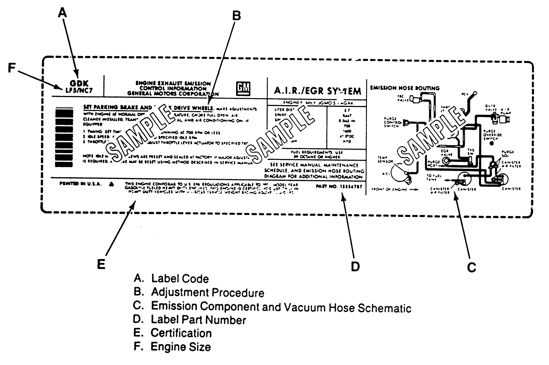
Fig. 1 Vehicle emission control information label information. General Motors Corp.
illustrated, others similar
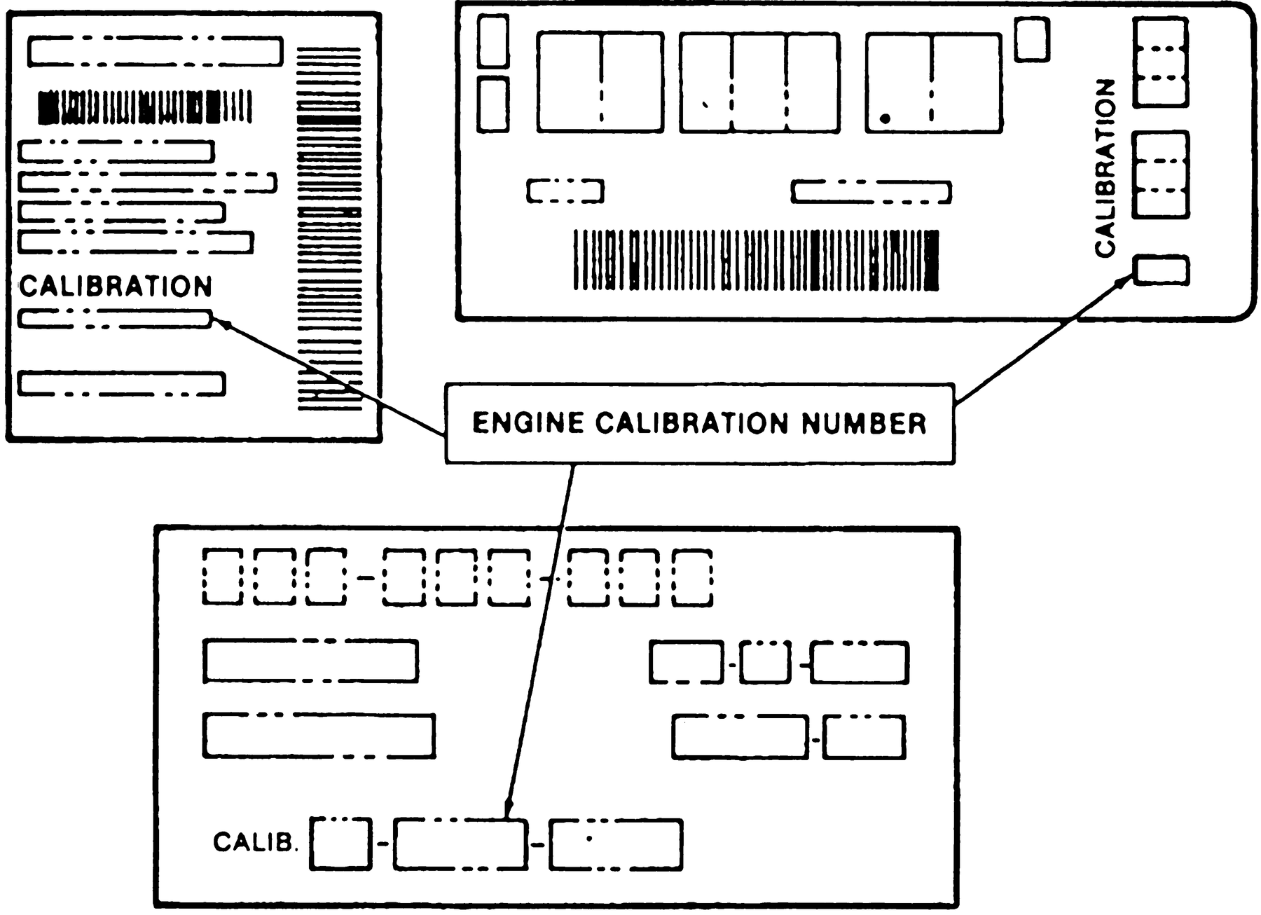
Fig. 4 Emission control calibration label information. 1975-88
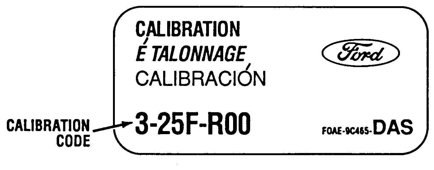
Fig. 5 Emission control calibration label information. 1989-2000
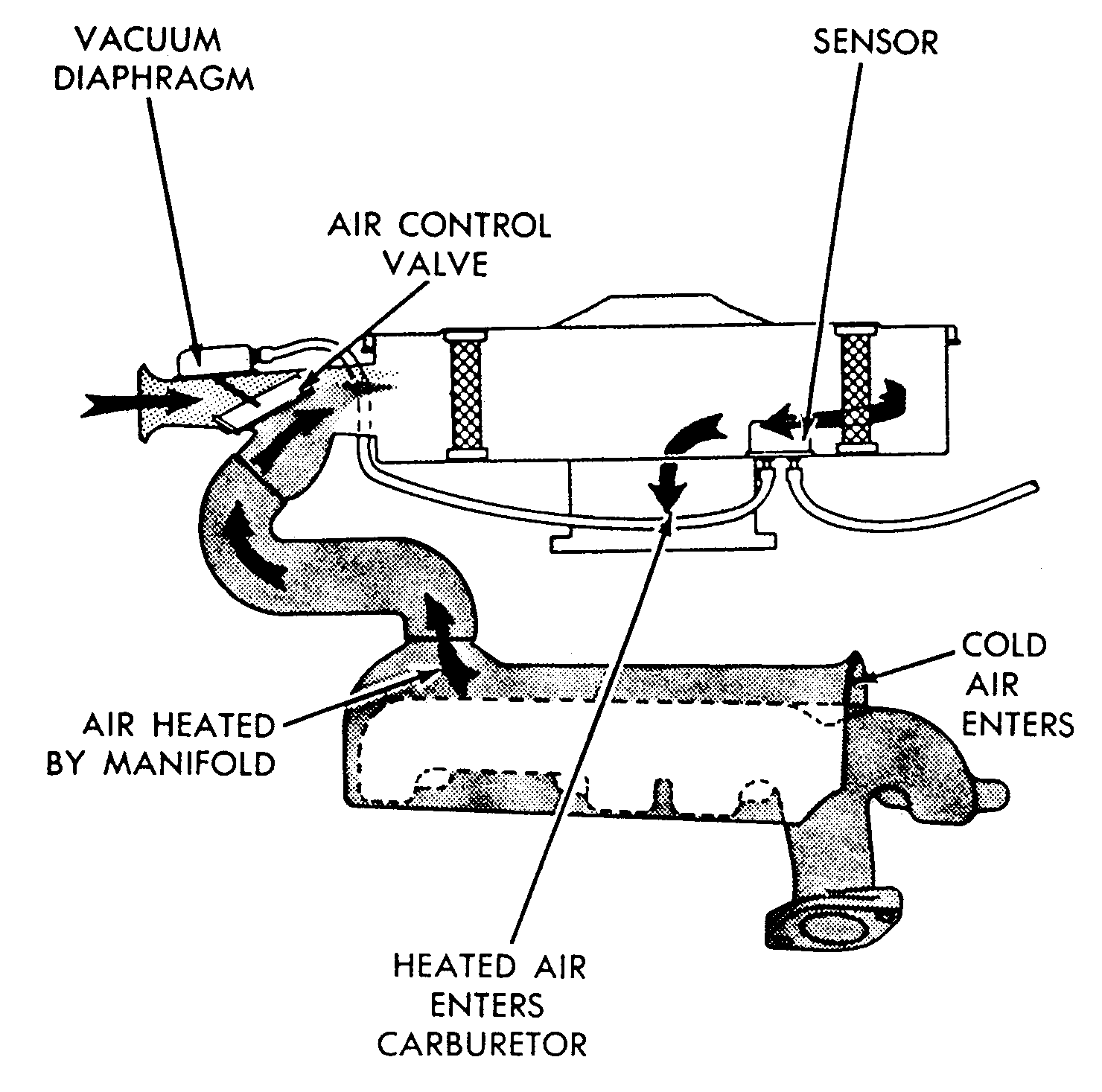
Fig. 6 Air cleaner (ACL) thermostatic type
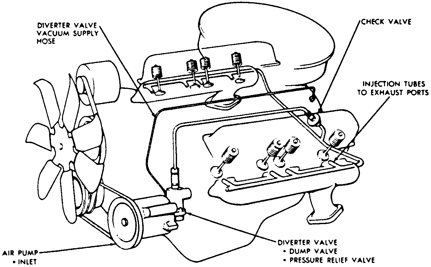
Fig. 7 Typical belt driven pump type air injection system
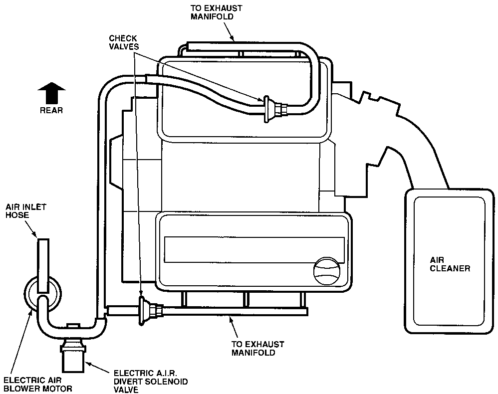
Fig. 8 Typical electrically powered pump type air injection system
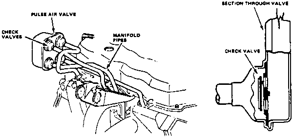
Fig. 9 Typical pulse (exhaust pulse) type air injection system
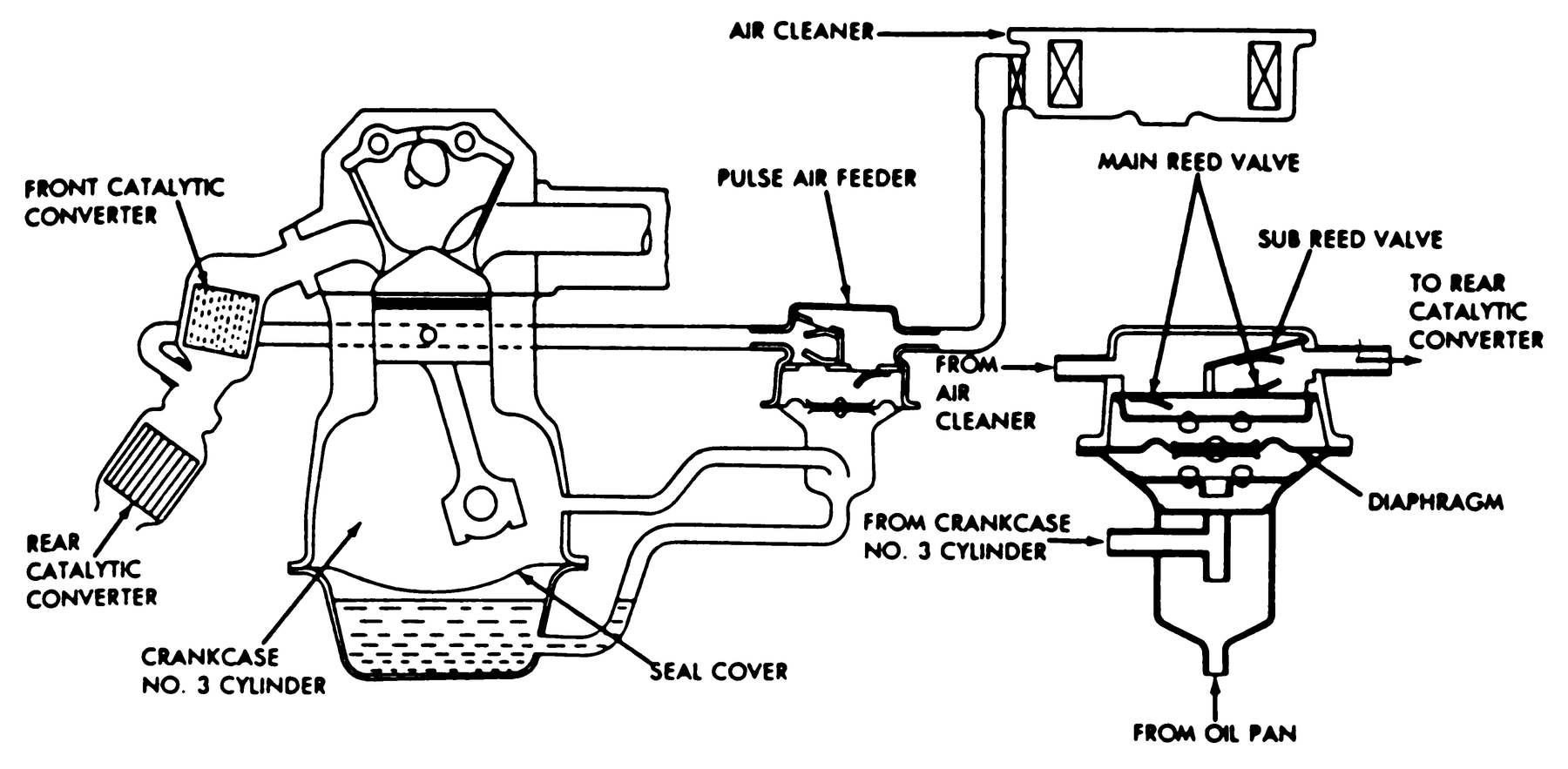
Fig. 10 Typical pulse (piston reciprocation) type air injection system
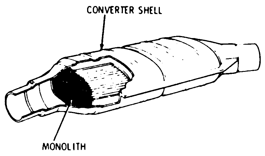
Fig. 11 Typical single bed monolith type catalytic converter
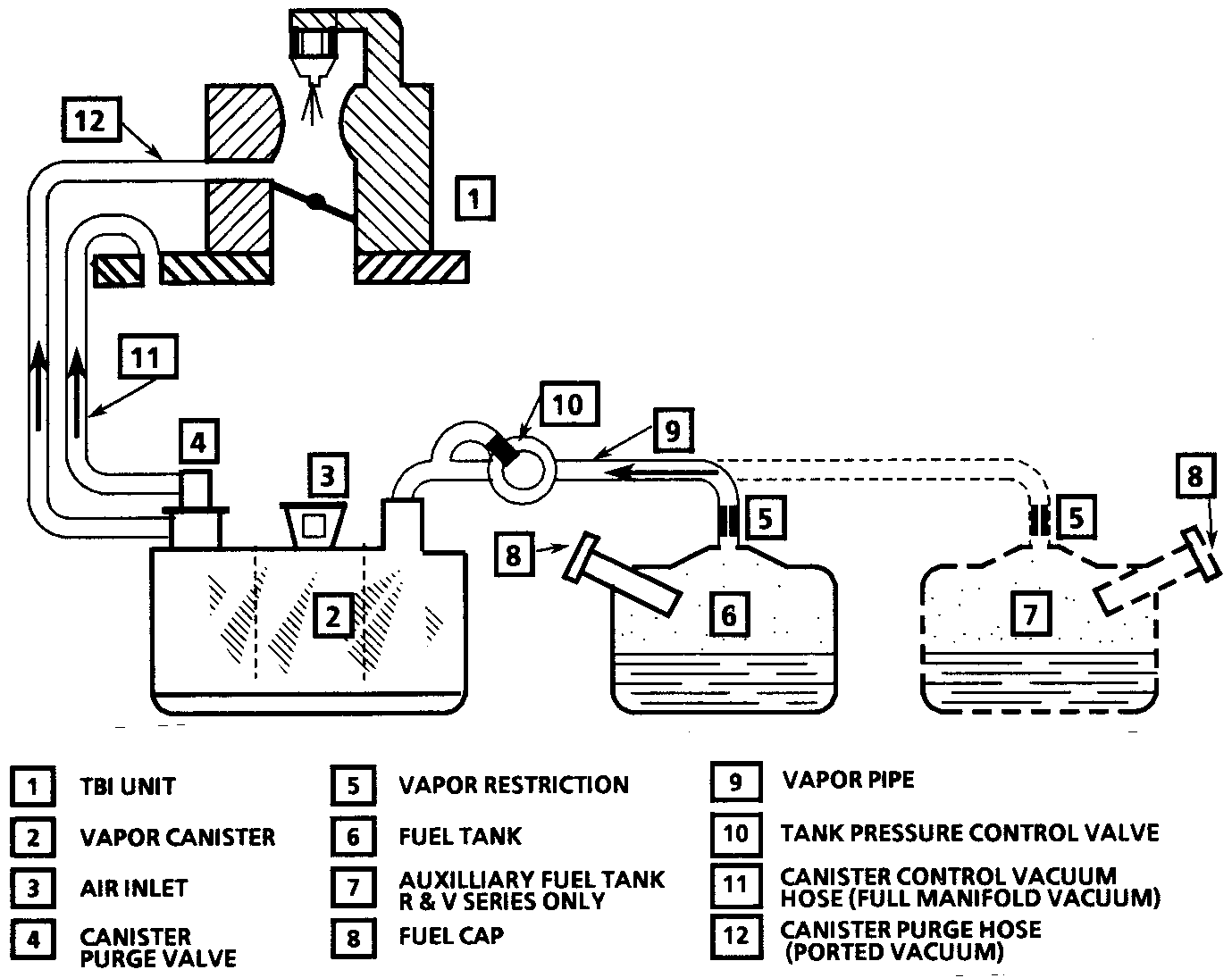
Fig. 16 Typical Evaporative Emission System (EVAP)
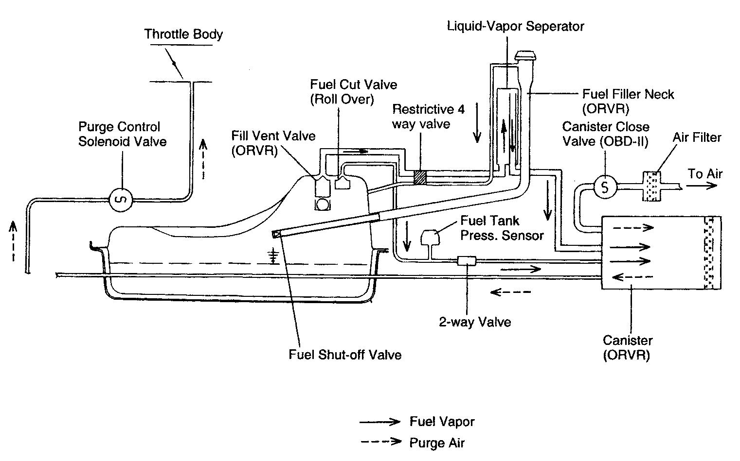
Fig. 17 Typical Evaporative Emission System (EVAP) with On-Board Refueling Vapor
Recovery (ORVR)
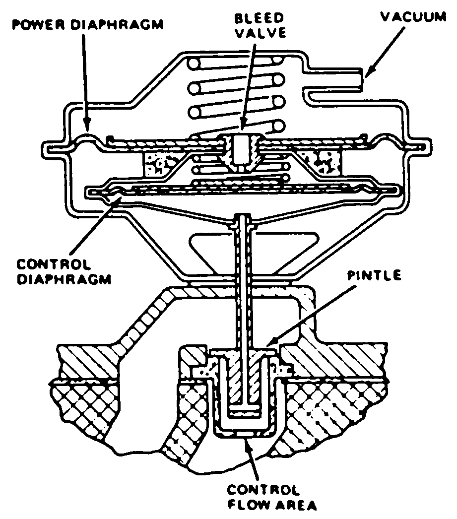
Fig. 18 Typical exhaust gas recirculation valve
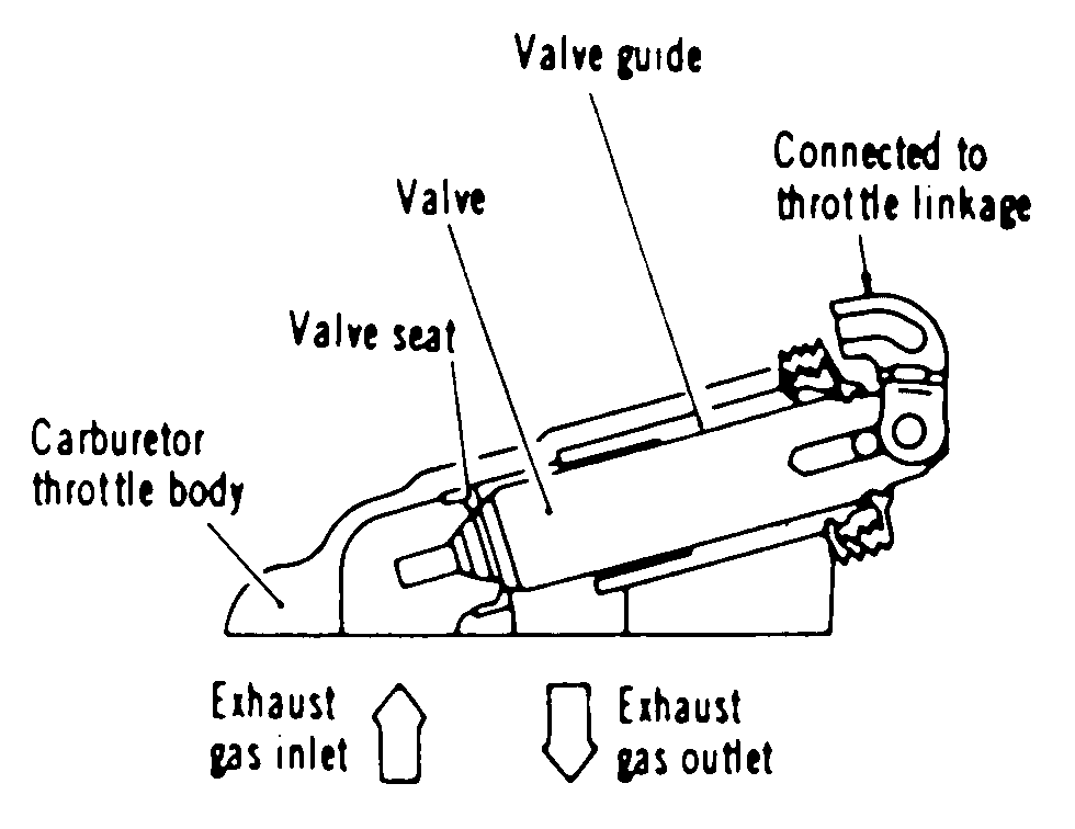
Fig. 24 Typical sub-exhaust gas recirculation valve
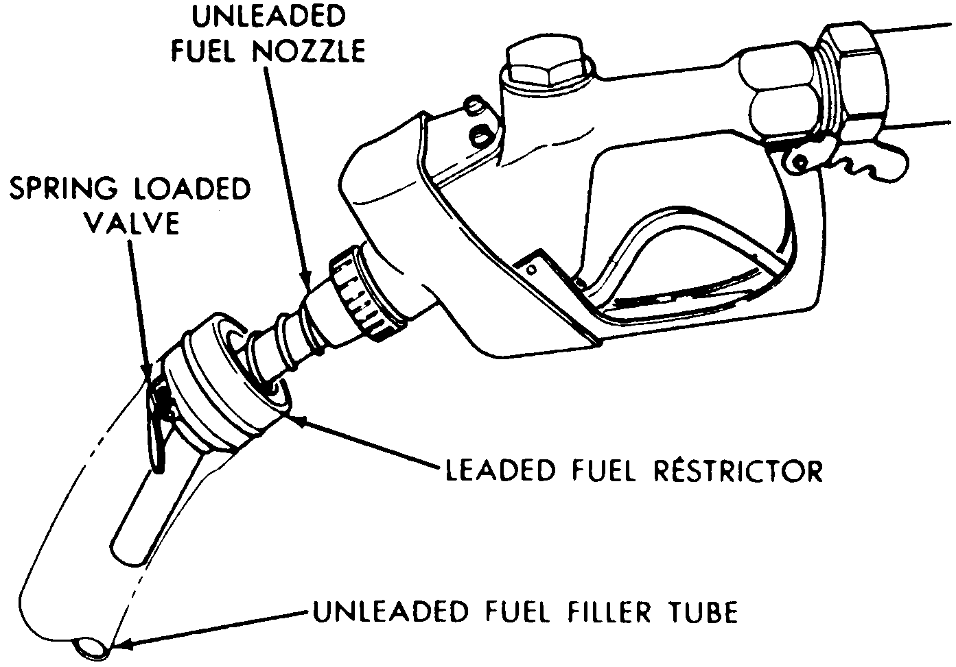
Fig. 25 Fillpipe restrictor
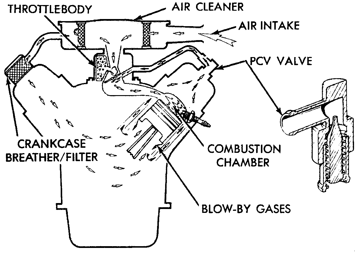
Fig. 26 Typical Positive Crankcase Ventilation (PCV) system
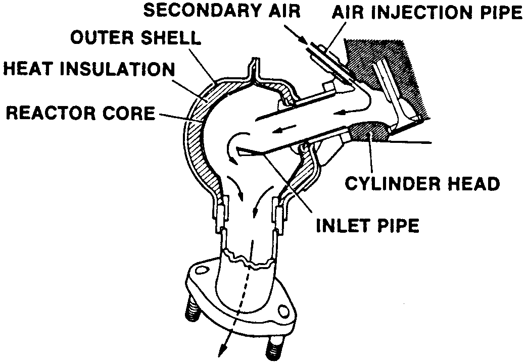
Fig. 27 Typical thermal reactor
FIG. NO.
BUICK:
EVAP System & Canister:
Centu ...
Fuel Injected Gasoline Engine
The EGR systems used on fuel injected
engines are controlled by the ECM. The ECM will store a code in memory when
the EGR system malfunctions. Refer to ap ...
See also:
Chevrolet Cobalt Owners Manual. New Vehicle Break-In
Notice: The vehicle does not need an elaborate
break-in. But it will perform better in the long run if
you follow these guidelines:
- Do not drive at any one constant speed,
fast or slow, for the first 500 miles (805 km).
Do not make full-throttle starts. Do not
exceed 5,000 engine rpm. Avoid
...


 General Motors Co.
 EGR Functional Tests